A few years ago I designed a pinwheel escapement in Lego inspired by Galileo's scheme. Galileo was the first person to suggest that a pendulum might be used to regulate a clock: you can read about Galileo's life and work here.
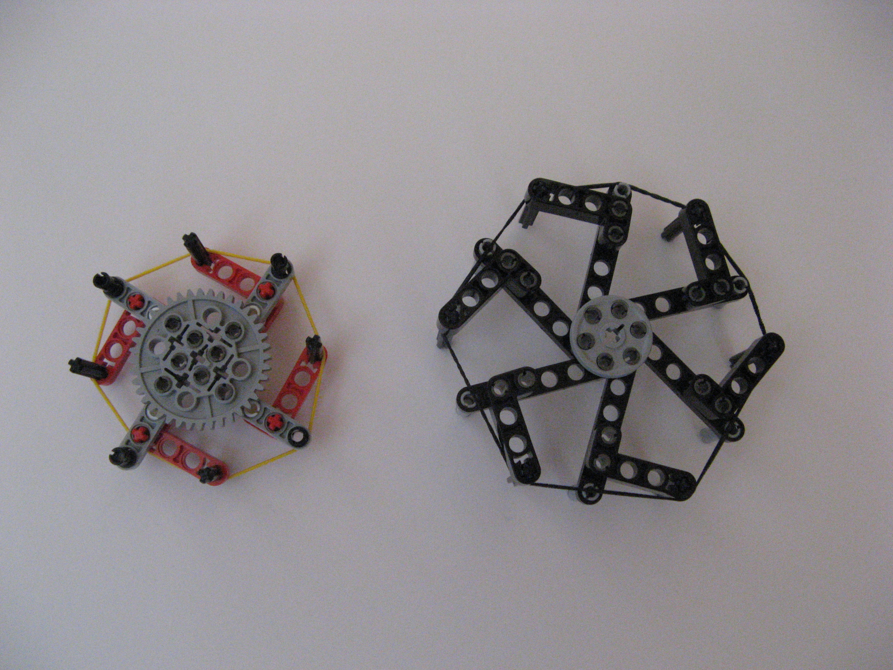
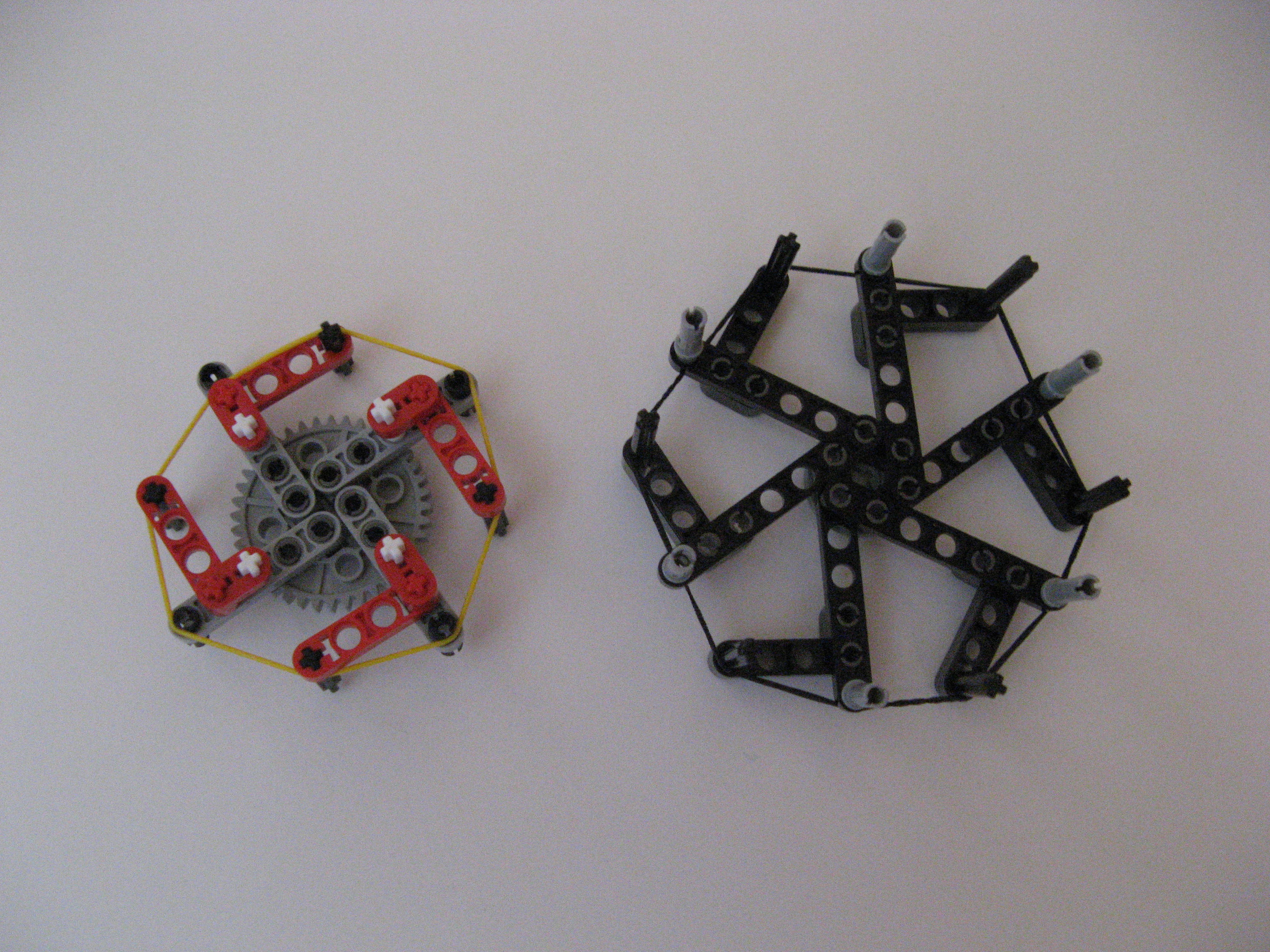
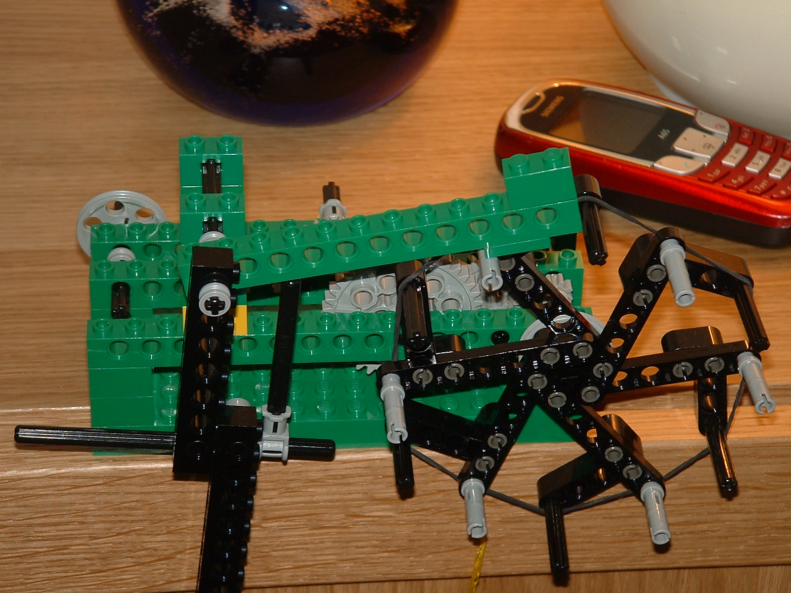
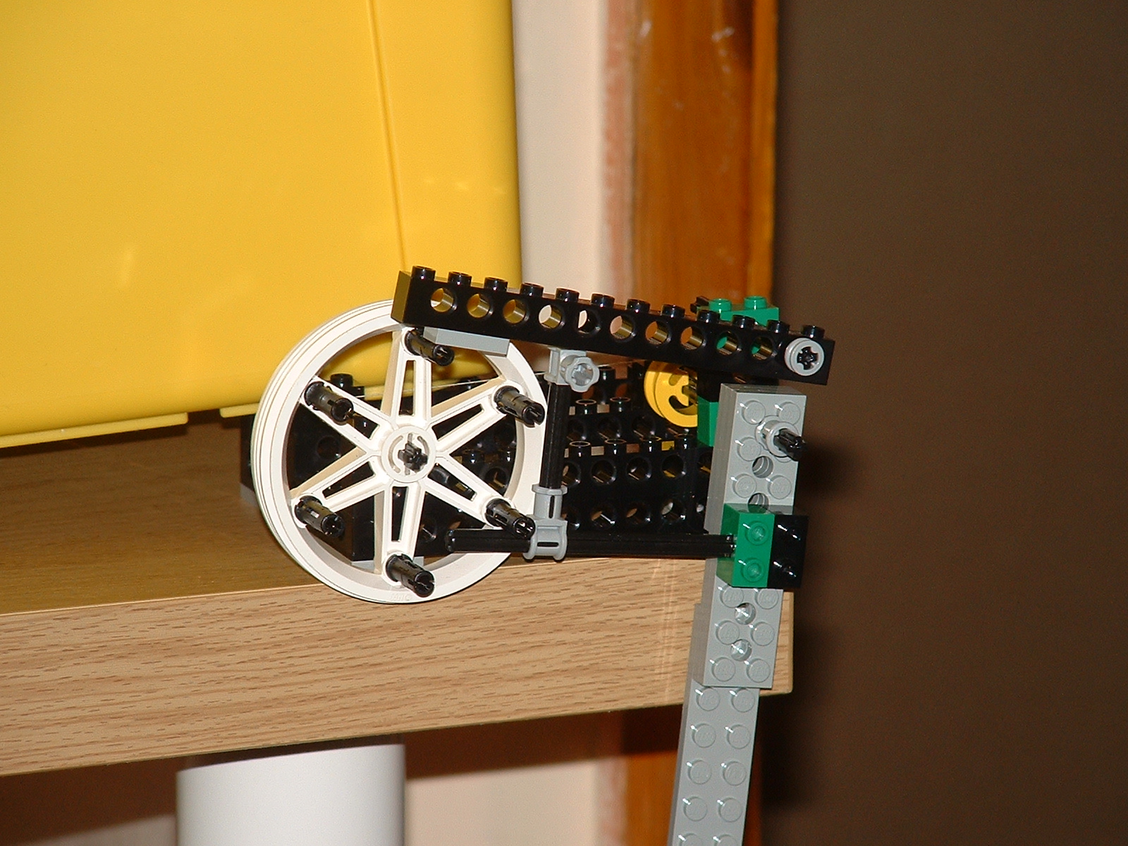
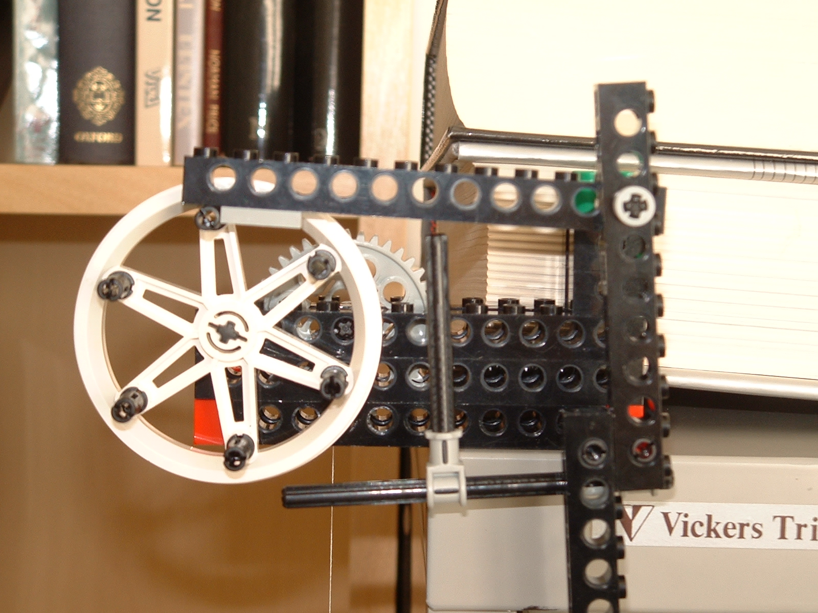
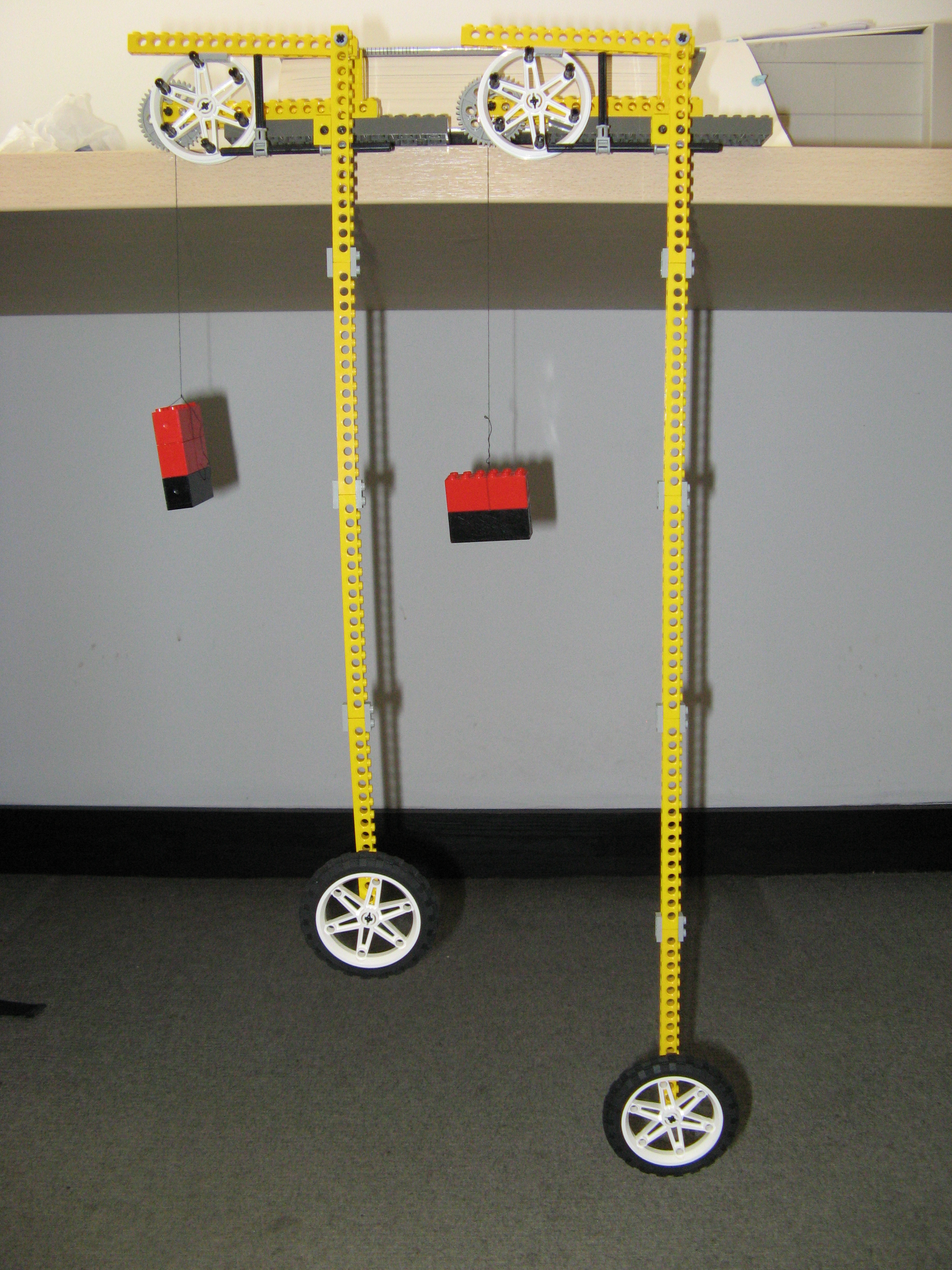
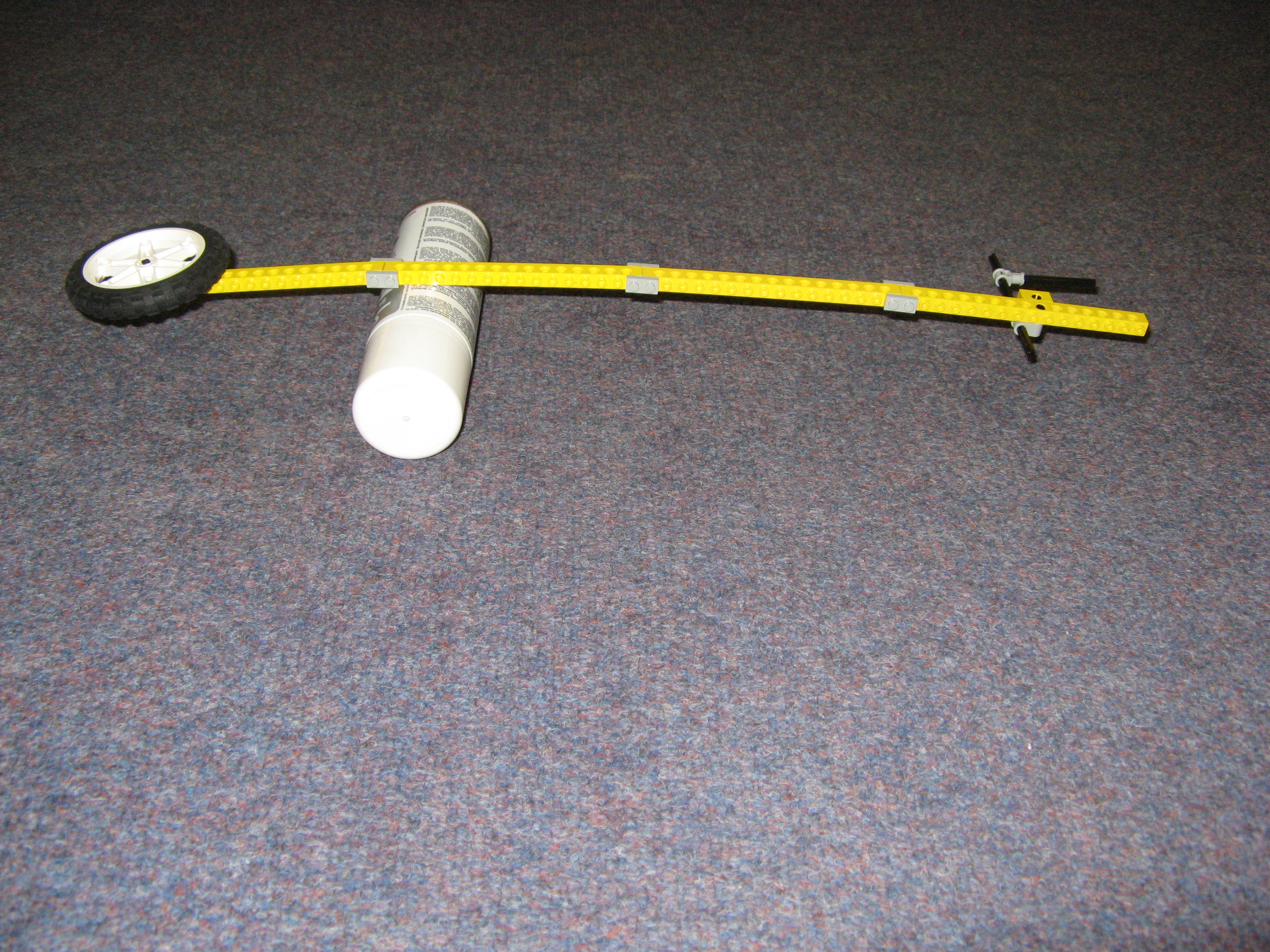
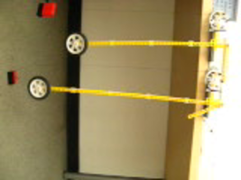
Here are some pictures of my original prototypes along with a couple of videos showing the movement in action.
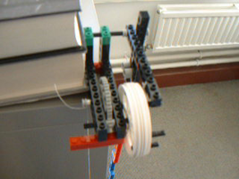
The thumbnail pictures on this page expand if you click on them.
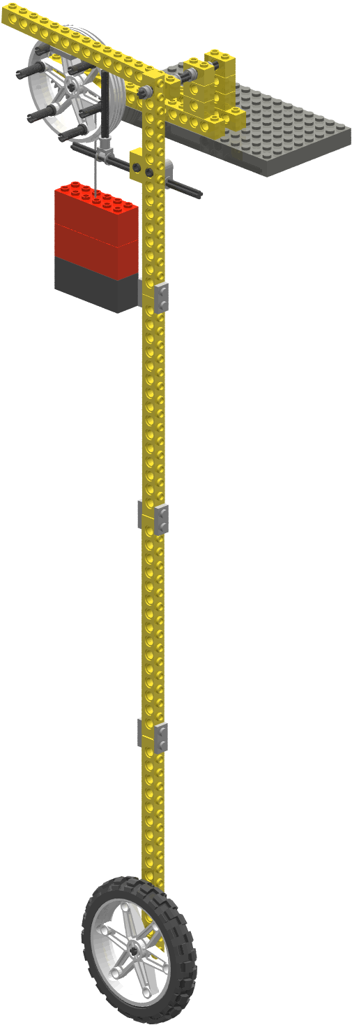
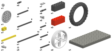
I've now designed a slightly improved version which uses the same basic geometry but with a reduced and standardised set of parts: here's a CAD drawing of the final version.
I've used the well-known MLCad and LPub tools to create a set of build instructions. Click on the Lego parts below to enter the build sequence.
It is important to make sure that you count studs in the drawings and place parts in exactly the right place. For instance in step 10, the grey 1x2 plate should be between the ninth and eleventh hole from the pendulum end of the beam or the escapement timing will be wrong. You only find out you've made an error when you've finished, and things don't actually run. Look at the photographs and videos on this page if in doubt.
The weight is attached in step 8. Thread some cotton through the circular bush and tie it on before putting the bush onto the axle. Then tie the other end round one of the weighted bricks. The other weights can then be just clipped on in the normal way. Wind the clock by turning the large gear wheel so that the thread wraps round the axle, not the bush. If you run it round the bush then more thread will be unwound for each revolution, and the clock will run down quickly. Try not to let the thread rub up against the yellow beam as you wind it otherwise the mechanism may bind.
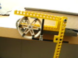
The horizontal arm is only just clearing the lowest peg on the escapement wheel, and the vertical arm is between the sixth and seventh hole in the lifting beam, counting from the pendulum end.
Make sure that the vertical arm is pushing the base of the pawl (the lifting arm that catches the escapement wheel). If you're unlucky, the axle will just slip between two of the studs on the underside of the lifting arm, and the arm won't move up far enough.
If you can't get a regular beat, by far the most likely problem is friction. Make sure that the gears move freely and aren't binding up against the supporting beams. Also make sure that the cotton suspending the weight hasn't tangled and isn't binding up against the support beam.
You can also try adding more weight. My versions run quite happily with about 150g suspended from the axle (not the bush). With only 100g performance may be unreliable. If you go too far and use a very heavy weight then operation may be too violent and you might miss steps as the wheel accelerates away before the lift arm falls back.
Lubrication can help too. Beware of oil-based lubricants as they may melt the plastic Lego gears. I use Servisol SUPER 200 which is a spray-on PTFE (Teflon) lubricant. It works well, and doesn't seem to cause any damage to Lego. A Google search should find you a supplier.
Here's a fly-by video of a working escapement to help you iron out any problems.
Torque is a force acting at a distance to twist an object. When we turn an axle, we are applying torque. For a given force, we get a higher torque if we apply it further from the axis of rotation. It is easier to turn the escapement wheel by pushing directly on its rim than by twisting its axle because the leverage effect of the larger diameter wheel means that a smaller force is needed to overcome the friction and inertia. On the other hand, that smaller force has to move through a greater distance - we don't get something for nothing.
Gears divide torque down. Try unwinding the weight and moving the bush to the escapement wheel axle. You will find that you need much less weight to turn the mechanism, but that the thread unwinds more rapidly. The large gear wheel has 40 teeth, and the small only eight teeth, so there is a 5:1 reduction ratio. You should find, therefore, that you only 20% of the weight but that the mechanism runs down five times faster.
Even taking into account the effective length of the pendulum, the escapement still seems to run faster than the pendulum formula predicts. It turns out that this is because the escapement mechanism pushes the pendulum before it has reached the top of its swing, so it starts falling back again earlier than it would if it was swinging freely.
The exact effect is hard to predict and is to some extent affected by the driving force since a heavier weight will accelerate the wheel more rapidly, and it will then push the pendulum earlier in the cycle. More significantly, changing the length of the horizontal pendulum arm can alter the point in the cycle at which the wheel pushes the pendulum.
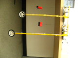
To demonstrate this effect, here are the same two pendulums swinging but with the lifting pawl moved out of the way so that the pendulums are not being driven by the escapement: they're just swinging freely and will eventually run down.
A rough check shows that the short pendulum performs around 11.5 oscillations in 15s and the long one around 10.
Clock makers try to make escapement mechanisms which perturb the pendulum swing as little as possible since so as to increase accuracy. The accuracy of a clock based on this escapement would be further compromised because it is temperature dependent: the horizontal pendulum axle will expand in hot weather. In fact, the pendulum rod would also expand, and that would change the pendulum's natural period. Beginning in the early eighteenth century, a variety of designs of temperature compensated pendulums were produced: the basic idea being to make the pendulum rod out of several bars of differnt metals which expanded different amounts in such a way as to keep the centre of gravity of the entire pendulum at a constant distance from the pivot.
The ultimate goal would be to make a clock with hours, minutes and seconds faces that would run for 24 hours between windings. I think this is probably not achievable with standard Lego parts, unless you live at the top of a tower block and are prepared to let the weight descend a long way... or you could try a heavy weight attached to a gear further away from the escapement wheel.